In case you haven’t gathered from previous posts, I’m quite into Z-Wave and Home Automation right now. Our existing wireless doorbell gave up the ghost a little while ago and I thought it was the perfect opportunity to get a Z-Wave doorbell so that I could integrate it into some areas of the house instead […]
In case you haven’t gathered from previous posts, I’m quite into Z-Wave and Home Automation right now. Our existing wireless doorbell gave up the ghost a little while ago and I thought it was the perfect opportunity to get a Z-Wave doorbell so that I could integrate it into some areas of the house instead of just a dumb chime unit nowhere near the living areas where we stand a chance of hearing it.
I used the article Do You Sell a Z-Wave Doorbell over at my favourite Z-Wave UK reseller, Vesternet for a little inspiration but since the article was written things have moved on a little.
If you have a wired doorbell running on mains voltage then this is actually a bit easier to accomplish as you can use the Fibaro Binary Sensor however I don’t have an existing wired doorbell as there is no wiring to support one so it’s wireless all the way. Since speaking to Vesternet about the project originally, Fibaro have released the new Universal Door and Windows Sensor which is a Generation 5 Z-Wave device meaning longer range and improved battery life so this is obviously the device I purchased for the project. It also has some differences from the previous model.
Follow me beyond the fold for the what parts I used and how I bond them all together.
The Doorbell
To start the ball rolling, we need a doorbell. I’ve used Byron doorbells in the past and they seem to work pretty well and the Byron Sentry BY401W has really good reviews on Amazon for range and battery life and at only £19, I was sold. The doorbell is a wireless unit with a weather resistant outdoor button and a wireless indoor receiver and chime unit. Nothing smart or complicated here, just feed batteries to the two units and you have a working doorbell. The outside button itself is not the prettiest thing but here, I’m looking for substance over style.
The Z-Wave Sensor
The Z-Wave Sensor, as I already eluded to is the Fibaro Universal Door and Window Sensor. The Fibaro sensor has a pair of terminals for connection to a volt free input. This means we can trigger the Fibaro sensor into an active state by pressing a button or throwing a switch.
By tying the sensor to something on the circuit board inside the doorbell receiver we can sense that button press and trigger the Fibaro sensor. The catch of course is that this is a volt free, dry contact sensor so we can’t fire voltage down there or we would fry the Fibaro sensor. It’s also worth noting that when used as an external sensor, we do not need the magnetic contact that Fibaro provide as this is used when you are working in door or window sensing mode. Leave the magnet it in the box or throw this away, up to you as we will not be needing it.
The important thing to note here is that the sensor available now is the newest Generation 5 Fibaro Door and Window Sensor, not the original one shown in the Vesternet article and there are differences as we will discover.
The Relay
To get around the dry contact issue, we use a normally closed relay. The relay acts as an intermediary in the circuit. On the contact side of the relay, we connect up to the circuit of the doorbell. When the doorbell is pressed, the voltage on the Byron circuit board will reach the relay coil and energise it. When connected to the normally open side of the relay, this will close (make) the circuit. When connected to the normally closed side of the relay, this will break (open) the circuit.
Relays come in so many different flavours, we need to be careful what we order to make sure it’s compatible with the Byron circuitry. The Byron receiver takes three AA batteries. With an output of 1.5 volts each, there is 4.5 volts on tap however to my mind, that was an odd voltage to power a speaker so I didn’t want to take that for granted, I wanted to test the Byron circuitry for a suitable contact point and the voltage to be sure.
After some poking around, I found that the best place to get voltage was from the speaker terminals. As I suspected however, we don’t see 4.5 volts here but a variable voltage between 0.5 volts and 1.5 volts. The reason the voltage is variable is because there is meant to be a speaker here, speaker input voltage goes up and down to determine the throw on the driver.
After a bit of searching on RS Components, I found this TE Connectivity relay to be suitable. It’s a DPDT relay which means it has eight pins. Two for contact, two for common, two for normally open and two for normally closed. Although I only need four, it does offer some flexibility if you want to mix things up a little or drive a secondary output as well as the Fibaro sensor and it was just over £1 with free delivery as always from RS Components.
The Wiring
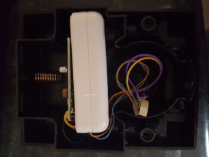
The wiring for this is actually really simple so long as you can hod your soldering iron still enough to get on the tidy relay pins. As I have no interest or need for the Byron chime, the speaker itself was dumped making room for the Fibaro sensor and the relay and wiring inside the original enclosure making it super neat and stock looking. If you wanted to keep the Byron internal speaker, you would need to have the Fibaro sensor externally situated which wouldn’t look terrible but it’s just something to bear in mind.
For the wiring itself, we need four wires. By de-soldering the points on the speaker, I was able to re-use the yellow and purple wires into the circuit board. De-soldering from the speaker end was less fiddly than trying to de-solder the PCB end. The next wire solders to one of the common pins on the relay and the last wire to the normally closed pin on the same side as the common pin. As this side is voltage free and we are using this extra pair just to close a circuit, the gauge of wire is not important so I stripped a piece of Cat 6 cable and took the blue and brown strands out and used those. The don’t need to worry about the gauge on the contact side as Byron covered that for us.
Relays as not polarised typically so we don’t need to worry about positive and negative terminals. Just make sure to get the right wires to the right pin and the polarity will sort itself out. Below is a basic illustration of how the wiring logically works. As you can see, we use the COM and NC (Normally Closed) relay pins on one side. The other side can be used to drive a secondary output if desired.
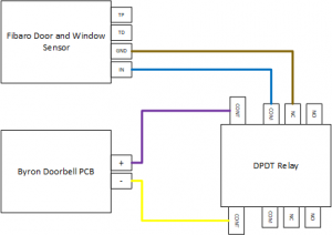
The terminals on the Fibaro relay are screw type which means no soldering required at this end.
Below is how the finished article looked. I applied some hot glue over all of the soldered areas and empty relay pins to prevent anything potentially shorting out once tucked up inside the Byron doorbell enclosure. As the relay is designed to be PCB surface mounted, the pins are very small not giving you a lot of soldering space so this also helps to hold the solder joints and wires in place.
Reassembly
When trying to seal the Byron doorbell receiver enclosure back together, I found that there were some locator lugs on the inside of the cover. When the speaker is installed, these help hold the speaker in place but due to the size of the Fibaro Door and Window Sensor, they were slightly holding off the cover so using a pair of pliers and a flat bladed screwdriver, I carefully chipped these away to make the inside edge flat which allowed the lid to screw down nicely without any obstruction.
The Z-Wave Configuration
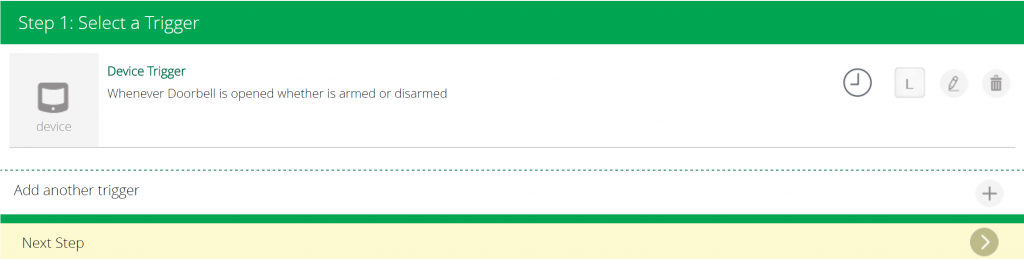
With our wiring and circuit complete, it’s time to make some Z-Wave magic happen. Follow the instructions in the Fibaro manual for inclusion and add the device to your Z-Wave network which in my case is a Vera Edge controller. I found that the Fibaro instructions which state to press the tamper button three times didn’t work and I had to spam the tamper button until Vera saw it which ended up being about nine presses in my case.
With the sensor included in the Z-Wave network, it should be correctly showing as idle (not tripped). Pressing the button on your doorbell button should light up the sensor red to indicate that it is tripped. If you see it double or triple flash, red, back to grey and then to red again, I’ll explain that in a moment.
In the Vesternet instructions, they talk about setting configuration Parameter 3 to change the mode from normally closed to normally open. This new Generation 5 sensor appears to lack that parameter as Parameter 3 instead controls the operation of the LED indicator. If you used a normally open relay then you will need to look at setting Parameter 1 which changes the mode from door/window sensor to external button mode but I wanted to avoid any extra configuration which was why I went for normally closed.
How you proceed from this point on is up to you. You may want to turn on a light, play a sound, send a push notification somewhere. In my case, I have the Sonos plugin for Vera installed which can play an alert through all of my Sonos speaker zones in the house giving me a house-wide doorbell sound.
I use the activation of the Fibaro sensor as a scene trigger and that triggers an Advanced action on the Sonos plugin to play an alert through all of our zones. The doorbell sound comes from an MP3 file hosted on a Windows Server 2016 Nano VM that I have running at home for messing around with.
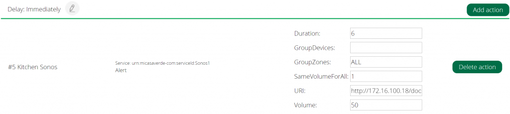
The Sonos plugin is great as it allows me to configure which zones play the alert, the volume used to play the alert and just as importantly, by defining the duration setting, the Sonos players will automatically revert to their previous state once the doorbell is done. If the zone was stopped, it goes back to being stopped. If a zone was playing the radio or Spotify at a particular volume, that’s what it goes back to.
The Double Activation Problem
This issue may or may not effect everyone which is why I’ve kept it as a footnote.
Because I have used the speaker contacts for wiring up the relay and because of the way in which we power a speaker, I noticed very quickly that my doorbell was actually double firing. There wasn’t a delay, the second fire was immediately after the first but still, the effect was undesirable. From an electrical standpoint, there is nothing I can do about this as I’ve already made by bed however I can control this in Vera using some conditional scene logic.
I found a perfect Luup code example to use on the MiCaseVerde forums at http://forum.micasaverde.com/index.php?topic=18679.120. The code is below. You need to paste this into the Luup Code editor in the scene that you create and customise the value of local twSecs to suit your taste. I used 30 seconds as a value. This Luup code will block the scene for the doorbell from executing if it has already been executed with the last 30 seconds (or whatever value you chose).
local twSecs = 30		-- Number of seconds in time window
local tNow = os.time()
local tLastOn = tLastOnD99 or 0
tLastOnD99 = tNow
return ((tNow - tLastOn) >= twSecs)
Fin
Well that’s a wrap, we’ve completed the project and we now have a fully functional Z-Wave wireless doorbell which integrates with the existing investments in the house, Sonos in my case. For me, this is a great solution. Not only do I get to hear the doorbell throughout the house but it’s also unobtrusive. With each speaker returning to it’s previous state after the chime plays,you hear the doorbell and then whatever was playing previously resumes automatically.
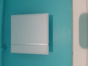
Here is a picture of the finished article. I’ve installed it on the wall in our utility room which is both out of the way and out of sight. It also happily happens to be roughly half way between the doorbell button outside and the Vera controller in my garage which means both sides of the wireless equation have great signal so reliability of the signals will not be an issue.
The next step for me is to now work on integrating the Philips Hue bulbs into this scene so that they flash a predefined colour to indicate the doorbell but this is going to be a lot harder than it would seem because of how unobtrusive I want it to behave to gain WAF (wife approval factor) and CAF (child approval factor).
Would I have done anything differently? Sure, two things actually. Firstly, the relay makes quite a loud click sound when it fires the contacts. If I was to do this over, I would look at paying the extra for a solid state relay so that there isn’t that moving part and there isn’t that audible clunk from the relay. Secondly, if I could, I would have liked to have been able to take a voltage feed from somewhere on the PCB with a more stable voltage so that I didn’t have to rely on conditional scene execution logic in Vera to block that double activation I am seeing but both of these are minor issues in reality.